PDP-7
S#2
S#33
S#34
S#41
S#47
S#103
S#104
S#109
S#112
S#113
S#114
S#115
S#118
S#126
S#129
S#148
S#150
FlipChips
History
Options
Teletypes
Digital Equipment Corporation PDP-7
Skip to navigation"FlipChip" Technology
 |
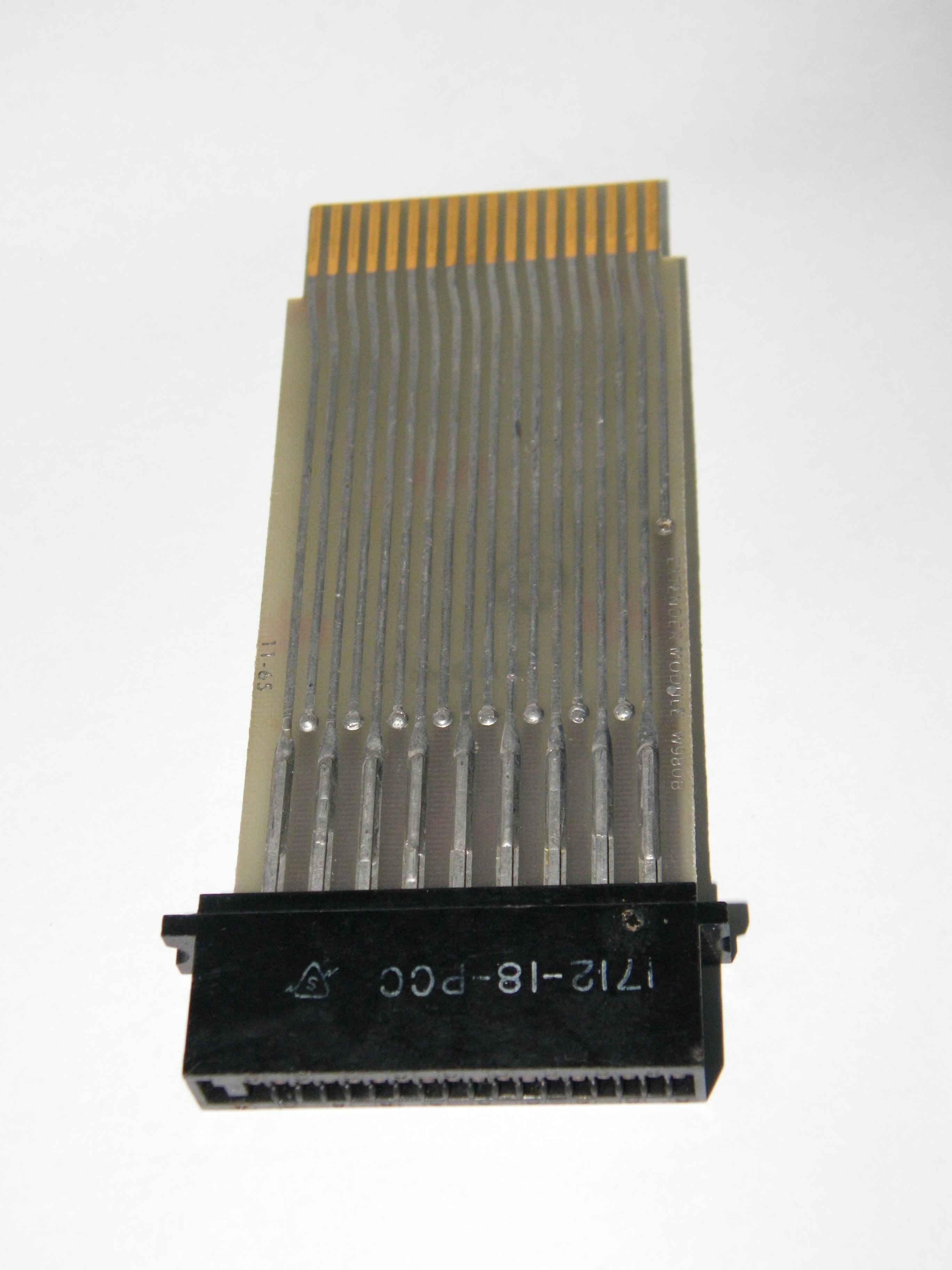 18 way extender board Click any image to enlarge Both ©2015 soemtron.org |
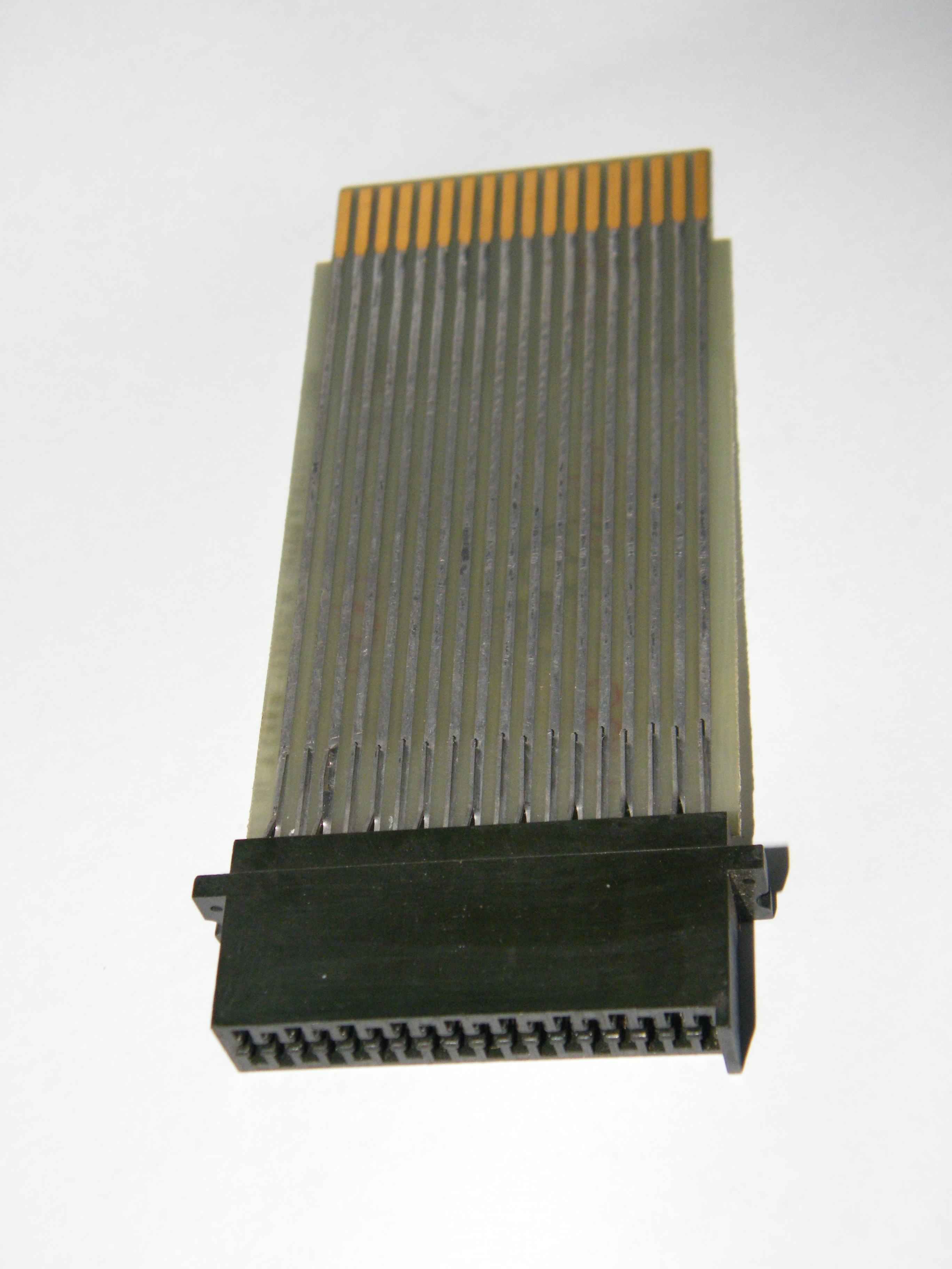 36 way extender board |
"FlipChip"[1] boards entered design in 1964 with the PDP-7 computer, as modules on boards 2.52" high by 5.0" long with an 18 pin edge connector of gold plated fingers plugged into a 144 pin edge connector block with a wire wrapped backplane. Each board had a colour coded handle for its generalised function and the technology used. Boards could be designed as a multiple of the 2.52" pitch with double and quad height boards being quite common. Towards the later stages of production 18 pins per board was found to be inadequate for the "new" integrated circuits, so the "FlipChip" design then went to double sided connectors yielding 36 pins for a single height board.
A number of the G and W-Series modules were redesigned on this new double sided form factor, and with careful attention to the board layout (as both the 18 pin and 36 pin boards could be plugged into the same connector), it allowed half of the circuits on the new 36 pin boards to be realised in an 18 pin connector position. The M-Series were first used in a redesigned PDP-8 machine, the PDP-8/I. There are eight board types in the series listed below, each with a different colour handle. This series information is roughly in chronological order.
Some confusion about the FlipChip trademark exists and did so even within DEC, the official "FLIP CHIP" trade mark was filed in August 1964[2] and registered in June 1966 with a serial number of 72200706, registration number 819864, it lapsed in March 1987. Various DEC manuals refer to the mark as "FLIP CHIP", "Flip Chip", "FLIP-CHIP", and "Flip-Chip", with both trademark and registered trademark symbols. For our purposes we refer to the brand as "FlipChip"
The DEC 1967 Logic handbook is a logic primer and list of data sheets covering some of the R, B and W-series "FlipChip" modules and includes 32 application notes (position decoding; stepper motor drives; pseudo random sequences Etc.). Sections also cover - Logic laboratory, Hardware (panels; cabinets; hardware; connectors; Octaid and Panelaid series modules; E and F Series modules), Analog to Digital Conversion handbook, A-series modules, K-series modules, and a whole lot more! [3], (X-series modules).
The "FlipChip" family[4] -
| Series | Handle | Description |
| R | (R)ed | Based on discrete components, as integrated circuits were still expensive, the R-series were diode and diode-capacitor-diode gates, with a range encompassing logic functions and signal conditioning to flip-flops running at up to 2MHz. |
| S | Red | Using the same circuits as the R-series but with component value changes to gain speed. 1963-1972. |
| B | (B)lue | Loosely based on the circuitry of the 10MHz 6000 Series of System Modules. Silicon based, the +10V bias supply required in the R and S-series boards was eliminated, but this restricted the gate depth to two as opposed to three as seen in the R and S-series boards. The B-series were first used in the PDP-7 range of computers, the range was further extended with usage in the PDP-10 series computers. 1963-1972. |
| A | (A)mber | Mainly analog functions, analog multiplexers, op-amps, sample and hold, D/A and A/D converters, references and other functions. 1963-1978. |
| G | (G)reen | system modules - core memory, peripheral devices, disk and tape controllers, terminals. 1963-1978. |
| W | (W)hite | I/O capability between other FlipChip units and other devices. The range includes lamp, relay and solenoid drivers, level converters, switch conditioning and cable termination. Blank boards were also provided for users to build their own circuits. 1963-1978. |
| K | blac(K) | Introduced in 1967 for I/O interfacing in industrial control and computing (100 KHz) uses. They were specifically designed to fit the NEMA package outline traditionally use in the industry but using the same 2.52" x 5.0" board outline and 18 pins connector scheme. During the development of the K-series modules integrated circuits were introduced for some of the logic functions. These units were marketed in 1967 and by 1975 there were about 200 different types of K-series modules. 1967-1973. |
| M | (M)agenta [5] | With the introduction of the M-series modules in 1967, the first from DEC to utilise integrated circuit logic functions based on the 7400 family of logic devices, the number of connectors per module was found to be a limiting factor. The M-series sought to rectify the problem by using a double sided board of 36 pins, again using the same 2.52" x 5.0" board outline. They were used in the redesigned PDP-8/I and the PDP-8E, the first PDP-11, the PDP-11/20 and the second PDP-10 processor (KI10). 1967-1978. |
If you know of any information about any of the PDP-7 systems worldwide, options, location of existing systems, spare parts, ancillary bits, software, tapes or manuals, then please contact us.
| 1 | FlipChip boards | Board data, a list of FlipChip modules including data, circuits and some PCB designs.[back] [top] |
| 2 | FlipChip trade mark information | United States Patent and Trademark Office Trademarkia[back] [top] |
| 3 | A find on the Google groups alt.folklore.computers has alerted us to another range in the "FlipChip" series, the X modules, Bob Clements writes - | "There were also X-series modules, they had a yellow handle. When I first saw these coming out of production I hit the dictionary to confirm my recollection that "xanthic" means yellow. But when I complimented the guy in charge of such things, he looked blankly at me. He didn't know from "xanthic". Yellow was just a colour that we hadn't used, and X was for Xerox, they were used in some 1970-ish large Xerox copiers". Only one card has come to light at the moment - Y006, "
G101 Display Board for PDP 8E" (original website unavailable). The images - Y006 handle - Y006 board - Y006 board text - are (C)2013 Kyle Owen. The original post was at - http://groups.yahoo.com/group/midatlanticretro/message/30390 - the pictures were at - http://imgur.com/a/d0iCD[back] [top] |
| 4 | FlipChip boards | See - "In the Beginning" a description of single and double height FlipChip boards and their originating reasons at Microsoft Research.[back] [top] |
| 5 | (M)agenta boards | Recent (12/22) information from Aron Insinga has a different explanation of the M series boards handle colour - The DEC M series logic modules had dark red handles so they were called "Maroon", not "Magenta". "M" could also stand for "Metal" since the large boards with metal handles and levers were also M series modules. In either case, they used IC's in DIPs. [back] [top] |
Site design ©2007- - privacy -